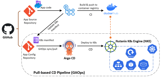
Integrate F5 Load Balancers into VMware Cloud on AWS SDDC Environment

With the recent release of VMware Cloud on AWS SDDC version 1.18, we have introduced a ton of advanced networking capabilities which opened up possibilities for many new interesting use cases. Customers can now utilise the NSX Manager UI (or VMC Policy API) to configure route aggregation at each SDDC level, and this provides an efficient way to solve the 100 DX route limit. Customer can also create additional Tier-1 Compute Gateways (Multi-CGWs) with static route injection capabilities to address different requirements such as network multi-tenancy, overlapping IPv4 environments and integrating with 3rd-party network & security appliances etc. You can read more details about the new features at here.

For this article we will focus on the use case of integrating 3rd-party load balancers into VMware Cloud on AWS. Specifically we will look at how to deploy and integrate a HA pair of F5 BIG-IP Local Traffic Manager (LTM) Virtual Edition (VE) into a SDDC cluster.

We will utilise the Route Aggregation and Multi-CGW features to create an inline load balancing topology and integrate with F5 LTMs within the lab SDDC cluster. Traffic from external towards the web servers will be routed through the F5 and the client source addresses are preserved (no SNAT is required and no need to configure XFF at the web servers)

prerequisites
  • Deploy a VMware Cloud on AWS SDDC cluster (ver 1.18+)
  • Access to F5 BIG-IP LTM VE (I’m using v16.1.2, a 30-day trial available here)
  • Access to an AWS account that is linked to the SDDC (so you can test connectivity via the connected VPC or VMware Transit Connect)
  • Deploy 2x web servers in SDDC for the LTM load balancing pool
Lab Procedures

I won’t cover every detailed step but at a high level we’ll need to perform the following tasks:

  1. configure SDDC route aggregation in NSX manager (so that Multi-CGW segment routes are advertised to the external)
  2. create 3x Tier-1 CGWs as per the below lab topology (1x routed CGW-LB-F5 for F5 Outside interfaces, 1x isolated CGW-LB-WEB for F5 Inside interfaces and the web segment, and 1x isolated CGW-LB-HA for F5 HA communications)
  3. create relevant network segments and attached to the above 3x CGWs accordingly
  4. configure static routes at the CGW-LB-F5 and CGW-LB-WEB for ingress and egress transit routing
  5. deploy the F5 LTM HA pair and configure network settings
  6. configure LTM load balancing settings (Nodes, Pool, VIP) and run tests
F5 Integration Lab Topology
STEP-1

To begin, we will first configure SDDC route aggregation at the NSX Manager UI. This will leverage an AWS managed prefix-list to announce summarised routes to external, so the Multi-CGW segments are accessible from connected VPC and Intranet (Direct Connect or VMware Transit Connect).

Within the NSX Manager UI, locate Networking > Global Configurations > Route Aggregation, create an aggregation prefix-list to summarise the SDDC CIDR block (172.30.0.0/16 in my case)

Then create a route configuration to announce the prefix-list to the INTRANET endpoint — since I’m using the VMware Transit Connect for my SDDC external connectivity, the summarised routes will be advertised to the VTGW.

Back at the VMC console we can verify the summarised route (172.30.0.0/16) is being advertised at the SDDC under Networking & Security > Transit Connect > Advertised Routes. Note the SDDC mgmt route (173.30.0.0/23) will not be summarised and will always be advertised explicitly.

STEP-2

Go to the NSX Manager again and create 3x Tier-1 CGWs as per the lap topology. Note we will need to select “routed” type for the CGW-LB-F5 in order to inject a static route towards F5 for the web server segment, and “isolated” type is required for the CGW-LB-WEB in order to inject default route (0.0.0.0/0) towards the F5.

STEP-3

Next, configure the below network segments as per the lab topology and attach them to the 3x CGWs accordingly. Note the VM-MGMT-NET01 is created at the default CGW and this is to host the F5 LTM management interfaces, which use a separate management route table.

STEP-4

Additionally, configure the CGW-LB-F5 to add a static route (for LB-F5-WEB01 segment) towards the F5 — the next-hop will be the Outside interface floating IP (172.30.100.10) between the LTM HA pair.

Similarly, configure the CGW-LB-WEB to add a default route towards the F5 — the next-hop will be the Inside interface floating IP (172.30.100.100) between the LTM HA pair.

STEP-5

We are now ready to deploy and configure the F5 LTM VE appliances. For the purpose of the demo I will only show the key network configurations of the LTM01.

Once the appliances are deployed and system has been initialised, go to each LTM management UI to configure the local network settings. First, create the data VLANs for each interface under Network > VLANs — notice here all VLANs are internal to F5 only and must be untagged at each interface, as VLAN trunking to a guest VM is not supported by VMware Cloud on AWS at this stage.

Next, configure the local interface IP addresses under Network > Self-IPs

Also add the static routes including default route under Network > Routes

At this stage, you are ready to add the peer device and create a HA failover device group. Once the device group is created and the HA pair is in sync, you can now create additional HA floating IP addresses for both the Inside and Outside interfaces.

Note here for the floating IPs you’ll need to apply a floating traffic group (I’m using the default traffic-group-1).

STEP-6

Finally we are ready to configure the load balancing settings at the F5 LTM HA pair for the workloads deployed in SDDC. For this lab I have deployed two simple Linux VMs with Apache web servers (172.30.101.11 & 172.30.101.12)

First, create 2x nodes for the web servers under Local Traffic > Nodes:

Second, create a LB pool at Local Traffic > Pools with the 2x nodes and select appropriate Health Monitor and Load Balancing Method.

Lastly, go to Local Traffic > Virtual Servers and deploy a HTTP VIP for the web service using the LB pool we have just created.

Assuming everything is configured correctly you should see the VIP coming online straight away, and you can also verify the service status at Local Traffic > Network Map:

Now hit the VIP address in your browser and you should see traffic is being load balanced between the two nodes (since we selected the basic Round Robin LB method).

and because the F5s are deployed in inline (routed) mode without SNAT, the web servers are able to see the original source IPs from the clients.

Provision and integrate iSCSI storage with VMware Cloud on AWS using Amazon FSx for NetApp ONTAP

With the recently announced Amazon FSx for NetApp ONTAP, it is very exciting that for the first time we have a fully managed ONTAP file system in the cloud! What’s more interesting about this service is that we can now deliver high-performance block storage to the workloads running on VMware Cloud on AWS (VMC) through a first-party Amazon managed service!

In this post I will walk you through a simple example for provisioning and integrating iSCSI-based block storage to a Windows workload running on VMC environment using Amazon FSx for NetAPP ONTAP. For this demo I’ve provisioned the FSx service in a shared service VPC, which is connected to the VMC SDDC cluster through an AWS Transit Gateway (TGW) via VPN attachment (as per below diagram).

Depending on your environment or requirements, you can also leverage a VMware Transit Connect (or VTGW) to provide high speed VPC connections between the shared service VPC and VMC, or simply provision the FSx service in the connected VPC so no TGW/VTGW is required.

AWS Configuration

To begin, I simply go to AWS console and select FSx in the service category and provision an Amazon FSx for NetApp ONTAP service in my preferred region. As a quick summary I have used the below settings:

  • SSD storage capacity 1024GB (min 1024GB, max 192TB)
  • sustained throughput capacity 512MB/s
  • Multi-AZ (ontap cluster) deployment
  • 1x storage virtual machine (svm01) to provide iSCSI service
  • 1x default volume (/vol01) of 200GB to host the iSCSI LUNs
  • storage efficiency (deduplication/compression etc): enabled
  • capacity pool tiering policy: enabled

After around 20min wait, the FSx ONTAP file system will be provisioned and ready for service. If you are using the above settings you should see a summary page similar like below. You can also retrieve the management endpoint IP address under the “Network & Security” tab.

Note the management addresses (for both the cluster and SVMs) are automatically allocated from within a 198.19.0.0/16 range, and the same address block is going to provide the floating IP for NFS/SMB service (so customers don’t have to change file share mounting point address during an ONTAP cluster failover). Since this subnet is not natively deployed in a VPC, AWS will automatically inject the endpoint addresses (for management and NFS/SMB) into the specific VPC route tables based on your configurations.

However, you’ll need to specifically inject a static route for this (see below) on TGW/VTGW, especially if you are planning to provide NFS/SMB services to the VMC SDDCs over peering connections — see here for more details.

Conversely, this static route is not required if you are only using iSCSI services as the iSCSI endpoints are provisioned directly onto the native subnets hosting the FSx service and are not using the floating IP range — more on this later.

Next, we’ll verify the SVM (svm01) and Volume (vol01) status and make sure they are all online and healthy before we can provision iSCSI LUNs. Note: you’ll always see a separate root volume (automatically) created for each SVM.

Now click the “svm01” to dive into the details, and you’ll find the iSCSI endpoint IP addresses (again they are in the native VPC subnets not the mgmt floating IP range)

ONTAP CLI CONFIGURATION

We are now ready to move onto the iSCSI LUN provisioning. This can be done by using either ONTAP API or ONTAP CLI, which is what I’m using here. First, we’ll SSH into the cluster management IP and verify the SVM and volume status.

Since this is a fully managed service, iSCSI service has been already activated on the SVM and the cluster is listening for iSCSI sessions on the 2x subnets across both AZs. You’ll also find the iSCSI target name here.

Now we’ll create a 20GB LUN for the Windows client running on VMC.

Next, create an igroup to include the Windows client iSCSI initiator. Notice the ALUA feature is enabled by default — this is pretty cool as we can test iSCSI MPIO as well 🙂

Finally, map the igroup to the LUN we have just created, make sure the LUN is now in “mapped” status and we are all done here!

Windows Client Setup

On the Windows client (running on the VMC), launch the iSCSI initiator configuration and put the iSCSI IP address of one of the FSx subnets in “Quick Connect”, Windows will automatically discover the available targets on the FSx side and log into the fabric.

Optionally, you could add a secondary storage I/O path if MPIO is installed/enabled on the Windows client. Like in my example here, I have add a second iSCSI session by using another iSCSI endpoint address in a different FSx subnet/AZ.

Now click “Auto Configure” under “Volumes and Devices” to discover and configure the iSCSI LUN device.

Next, go to “Computer Management” then “Disk Management” —> you should see a new 20GB disk has been automatically discovered (or manually refresh the hardware list if you can’t see the new disk yet). Initialise and format the disk.

The new 20GB disk is now ready to use. In the disk properties, you can verify the 2x iSCSI I/O paths as per below, and you can also change the MPIO policy based on your own requirements.

Integrating a 3rd-party firewall appliance with VMware Cloud on AWS by leveraging a Security/Transit VPC

With the latest “Transit VPC” feature in the VMware Cloud on AWS (VMC) 1.12 release, you can now inject static routes in the VMware managed Transit Gateway (or VTGW) to forward SDDC egress traffic to a 3rd-party firewall appliance for security inspection. The firewall appliance is deployed in a Security/Transit VPC to provide transit routing and policy enforcement between SDDCs and workload VPCs, on-premises data center and the Internet.

Important Notes:

  • For this lab, I’m using a Palo Alto VM-Series Next-Generation Firewall Bundle 2 AMI – refer to here and here for a detailed deployment instructions
  • “Source/Destination Check” must be disabled on all ENIs attached to the firewall
  • For Internet access, SNAT must be configured on firewall appliance to maintain route symmetry
  • Similarly, inbound access from Internet to a server within VMC requires DNAT on firewall appliance

Lab Topology:

SDDC Group – Adding static (default) route

After deployed the SDDC and SDDC Group, link your AWS account at here

after a while, the VTGW will show up in the Resource Access Manager (RAM) within your account, accept the shared VTGW and then create a VPC attachment to connect your Security/Transit VPC to the VTGW.

Once done, add a static default route at SDDC Group to point to the VTGW-SecVPC attachment.

the default route should appear soon under your SDDC (Network & Security —> Transit Connect), also notice we are advertising the local SDDC segments including the management subnets

AWS SETUP

Also we need to update the route table for each of the 3x firewall subnets

Route Table for the AWS native side subnet-01 (Trust Zone):

Route Table for the SDDC side subnet-02 (Untrust Zone):

Route Table for the public side subnet-03 (Internet Zone):

Route Table for the customer managed TGW:

Palo FW Configuration

Palo Alto firewall interface configuration

Virtual Router config:

Security Zones

NAT Config

  • Outbound SNAT to Internet
  • Inbound DNAT to Server01 in SDDC01

Testing FW rules

Testing Results
  • “untrust” —> “trust” deny
  • “trust” —> “untrust” allow
  • “untrust” -> “Internet” allow
  • “trust” -> “Internet” allow

Create a Tiny Core Linux VM Template for vSphere Lab environment

I’ve always wanted to find a lightweight VM template for running on nested vSphere lab environment, or sometimes for demonstrating live cloud migration such as vMotion to the VMware Cloud on AWS. Recently I have managed to achieve this by using the Tiny Core Linux distribution and it ticked all of my requirements:

  • ultra lightweight – the VM runs stable with only 1 vCPU, 256MB RAM and 64MB hard disk!
  • common linux tools installed – such as curl, wget, openssh etc
  • open-vm-tools installed
  • a lightweight http server serving a static site for running networking or load-balancing tests

In this post I will walk you through the process for creating a Tiny Core based Linux VM template including all of the above requirements. To begin, download the Tiny Core ISO from here. (For reference, I’m using the CorePlus-v11.1 release as I was getting some weird issues with OpenSSH on the latest v12.0 release)

Below are the settings I’ve used for my VM template:

  • VM hardware version 11 – compatible with ESXi 6.0 and later
  • Guest OS = Linux \ Other 3.x Linux (32-bit)
  • Memory = 256MB (this is the lowest I could go for getting a stable machine)
  • Hard Disk = 64MB – change drive type to IDE and set the virtual device node to IDE0:0
  • CDROM – change the virtual device node to IDE1:0
  • iSCSI controller – remove this as it’s not required

Also, you should use the below minimal settings for installing the Tiny Core OS. For detailed installation instructions, you can follow the step-by-step guide at here:

Once the OS has been installed and you are into the shell, create a below script to configure static IP settings for eth0 (and disable DHCP if required).

tc@box:~$ cat /opt/interfaces.sh
#!/bin/sh
# If you are booting Tiny Core from a very fast storage such as SSD / NVMe Drive and getting 
# "ifconfig: SIOCSIFADDR: No such Device" or "route: SIOCADDRT: Network is unreachable"
# error during system boot, use this sleep statement, otherwise you can remove it -
sleep .2
# kill dhcp client for eth0
sleep 1
if [ -f /var/run/udhcpc.eth0.pid ]; then
 kill `cat /var/run/udhcpc.eth0.pid`
 sleep 0.5
fi
# configure interface eth0
ifconfig eth0 192.168.0.1 netmask 255.255.255.0 broadcast 192.168.0.255 up
route add default gw 192.168.0.254
echo nameserver 192.168.0.254 >> /etc/resolv.conf
tc@box:~$sudo chmod 777 /opt/interfaces.sh
tc@box:~$sudo /opt/interfaces.sh

You may also want to reset the password for the default user “tc” (this can be used later for SSH access), and reset the root password as well:

tc@box:~$ passwd
Changing password for tc
...
tc@box:~$ sudo su
root@box:/home/tc# passwd
Changing password for root
...

Now install all the required packages and extensions, and your onboot package list should look like below:

tce-load -wi pcre.tcz curl.tcz wget.tcz open-vm-tools.tcz openssh.tcz busybox-httpd.tcz
tc@box:~$ cat /etc/sysconfig/tcedir/onboot.lst
pcre.tcz
curl.tcz
wget.tcz
open-vm-tools.tcz
openssh.tcz
busybox-httpd.tcz

Now configure and enable the SSH server — you can use user “tc” for a quick SSH test:

cd   /usr/local/etc/ssh
sudo cp ssh_config.orig ssh_config
sudo cp sshd_config.orig sshd_config
sudo /usr/local/etc/init.d/openssh start

Next, we’ll need to save all the settings and make them persistent across reboots, especially we’ll need to add the open-vm-tools and openssh onto the startup script (bootlocal.sh) — otherwise none of these services would be started after a reboot.

sudo su
echo '/opt/interfaces.sh' >> /opt/.filetool.lst
echo '/usr/local/etc/ssh' >> /opt/.filetool.lst
echo '/etc/shadow' >> /opt/.filetool.lst
echo '/opt/interfaces.sh' >> /opt/bootlocal.sh
echo '/usr/local/etc/init.d/open-vm-tools start &> /dev/null'  >> /opt/bootlocal.sh
echo '/usr/local/etc/init.d/openssh start &> /dev/null' >> /opt/bootlocal.sh

and most importantly, use the below command to backup all the config!

tc@box:~$ filetool.sh -b
Backing up files to /mnt/sda1/tce/mydata.tgz

The last one is for my own specific requirement — you can use the below script to setup a lightweight http server so it can be used for networking or load-balancing related tests.

tc@box:~$ sudo vi /opt/httpd.sh
sudo /usr/local/httpd/bin/busybox httpd -p 80 -h /usr/local/httpd/bin/
sleep .5
sudo touch /usr/local/httpd/bin/index.html
sudo chmod 666 /usr/local/httpd/bin/index.html
echo "this page is served by" >> /usr/local/httpd/bin/index.html
ifconfig eth0 | grep -i mask | awk '{print $2}'| cut -f2 -d:  >> /usr/local/httpd/bin/index.html
tc@box:~$ sudo chmod 777 /opt/httpd.sh
tc@box:~$ sudo echo '/opt/httpd.sh' >> /opt/bootlocal.sh
tc@box:~$ filetool.sh -b

Now you can go ahead and safely reboot the VM, and once it comes back online you should be able to SSH into it. Also the the open-vm-tools service should be automatically started and you can see the correct IP address and VM tool version reported in vCenter.

In addition, you should be able to see a static page like below by browsing to the VM address — the script (httpd.sh) should report back the VM’s IP address which could be handy for running a LB related testings.

NSX-T Automation with Terraform

Recently I have tried out the Terraform NSX-T Provider and it worked like a charm. In this post, I will demonstrate a simple example on how to leverage Terraform to provision a basic NSX tenant network environment, which includes the following:

  1. create a Tier-1 router
  2. create (linked) routed ports on the new T1 router and the existing upstream T0 router
  3. link the T1 router to the upstream T0 router
  4. create three logical switches with three logical ports
  5. create three downlink LIFs (with subnets/gateway defined) on the T1 router, and link each of them to the logical switch ports accordingly

Once the tenant environment is provisioned by Terraform, the 3x tenant subnets will be automatically published to the T0 router and propagated to the rest of the network (if BGP is enabled), and we should be able to reach the individual LIF addresses. Below is a sample topology deployed in my lab — (here I’m using pre-provisioned static routes between the T0 and upstream network for simplicity reasons).

Software Versions Used & Verified

  • Terraform – v0.12.25
  • NSX-T Provider – v3.0.1 (auto downloaded by Terraform)
  • NSX-T Data Center -v3.0.2 (build 0.0.16887200)

Sample Terraform Script

You can find the sample Terraform script at my Git repo here — remember to update the variables based on your own environment.

nsx_manager     = "192.168.100.125"
nsx_username    = "admin"
nsx_password    = "xxxxxx"
nsxt_t1_rt_name = "dev-demo-t1-rtr"
ls1_name        = "ls-dev-demo-web"
ls2_name        = "ls-dev-demo-app"
ls3_name        = "ls-dev-demo-db"
ls1_gw          = "172.31.101.1/24"
ls2_gw          = "172.31.102.1/24"
ls3_gw          = "172.31.103.1/24"

Run the Terraform script and this should take less than a minute to complete.

We can review and reverify that the required NSX components were built successfully via the NSX manager UI — Note: you’ll need to switch to the “Manager mode” to be able to see the newly create elements (T1 router, logical switches etc), as Terraform was interacting with the NSX management plane (via MP-API) directly.

In addition, we can also check and confirm the3x tenant subnets are published via T1 to T0 by SSH into the active edge node. Make sure you connect to the correct VRF table for the T0 service router (SR) in order to see the full route table — here we can see the 3x /24 subnets are indeed advertised from T1 to T0 as directly connected (t1c) routes.

As expected I can reach to each of the three LIFs on the T1 router from the lab terminal VM.